
In this episode I’m going to make a miniPET. Last time we unboxed the MiniPET kit computer from Tynemouth Software and The Future Was 8-Bit. This time we start to build it.
The kit is relatively straightforward to make; the parts come in separate bags for passive components, and a large antistatic bag for the ICs. Some components are a bit small and fiddly. Some you need to take care to get them the right way round. There’s a 74 page A5 glossy manual, printed in colour, with very clear diagrams showing where each piece goes. It’s very well laid out and has lots of supplemental information that will be useful (such as resistor colour codes). It’s also spiral bound, so it lies flat.
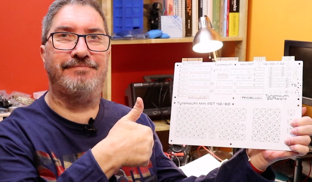
The only thing missing that I wish it had is a schematic. The PCB is so thickly covered with white paint that it’s almost impossible to see the traces. While this might make for a sleek looking computer that will be gorgeous in a display cabinet, it’s going to be a bit of a bugger to debug (!) if it doesn’t work first time, and you can’t easily follow any of the signals.
This board revision is markedly different to earlier ones (all the YouTube videos show the earlier revision), so won’t be as relevant to this one.
In part 1 we will fit the passive components: resistors, capacitors, as well as the chip sockets, connectors, DIP switches, diodes, LEDs, transistor and piezo electric sounder. If you’re making your own MiniPET (or planning to), you should allow a good couple of hours for this part, and probably 4 to 5 hours over all. There is a lot of soldering, and if you are not confident with a soldering iron, I’d recommend you practice for a while on something unimportant first.
Ultimately, what we’re doing here is not difficult, it’s all through-hole soldering (no surface mount), so I’d rate it a 2 on the difficulty scale.
I think we’re going to have a lot of fun with this!