
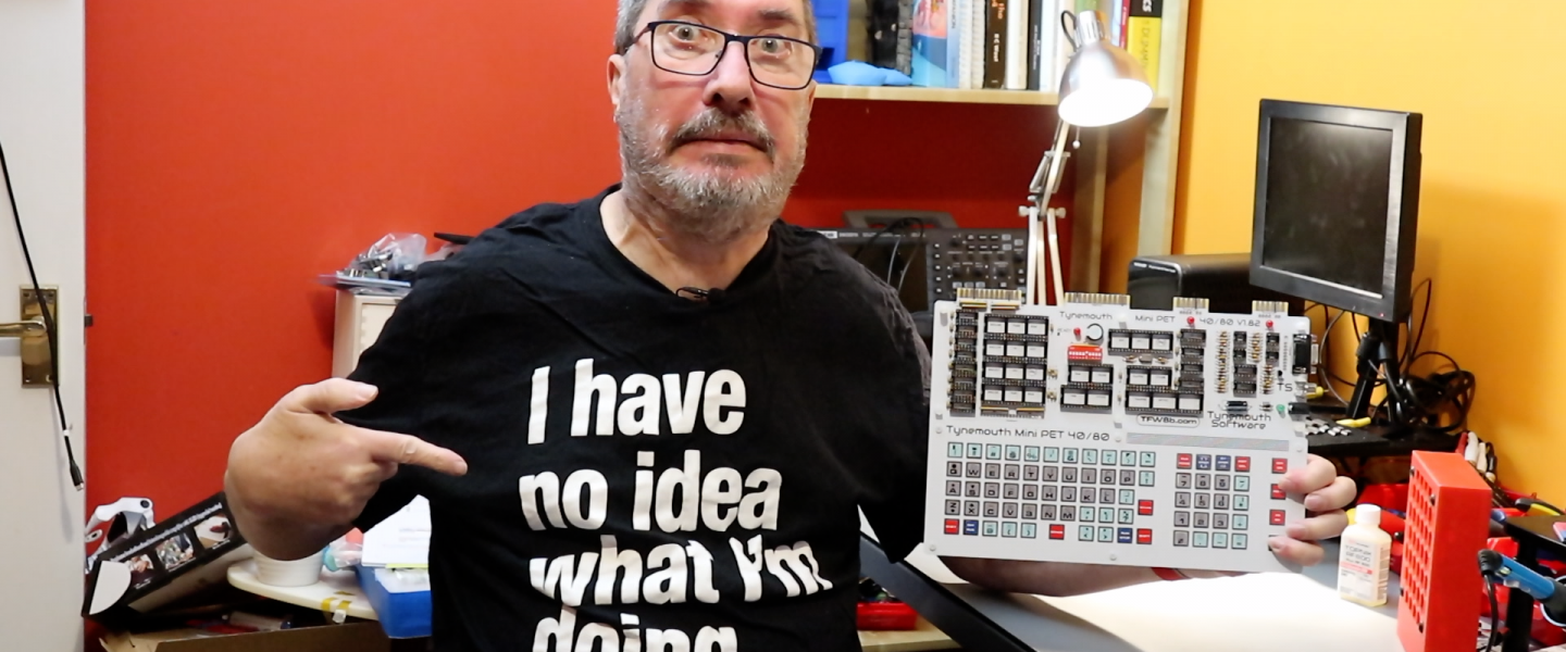
The MiniPET 40/80 is built, we plug it in, and . . . . nothing. It doesn’t work. There’s a short on the board in the worst possible way – directly between +5 volts and ground. We have to debug it if we don’t want it just to be an expensive paperweight.
So where do we start? There are no schematics for this board, the PCP is smothered in white paint so we can’t se the traces even. This means we have to go back to first principles. Start with the most likely and work towards the less likely.
Is it a faulty chip? Well I’ve removed all the ICs and it’s still shorted, so it’s not that.
Is something in backwards?
Is there a solder bridge between adjacent connections? Well this is the most likely, but a visual inspection with a magnifying lens doesn’t show anything. So maybe it’s lurking underneath a chip socket?
Well, I’m not going to spoil the fun by telling you what the problem was (yes I did fix it!) – you’ll have to watch the video for that. But I will say — with the advantage of 20-20 hindsight — that checking for shorts early in the build process, and ideally after each section, will prevent the need for drastic remedial action at the end of the project. If you’re thinking of tackling this project yourself (or any other similar project), it’s something to bear in mind.
The MiniPET does have some built-in diagnostics: there are two self-test modes that can be set through the DIP switches. Of course it does have to be working enough to get a display and run those tests. But once it does, it’s nice to see them all pass.
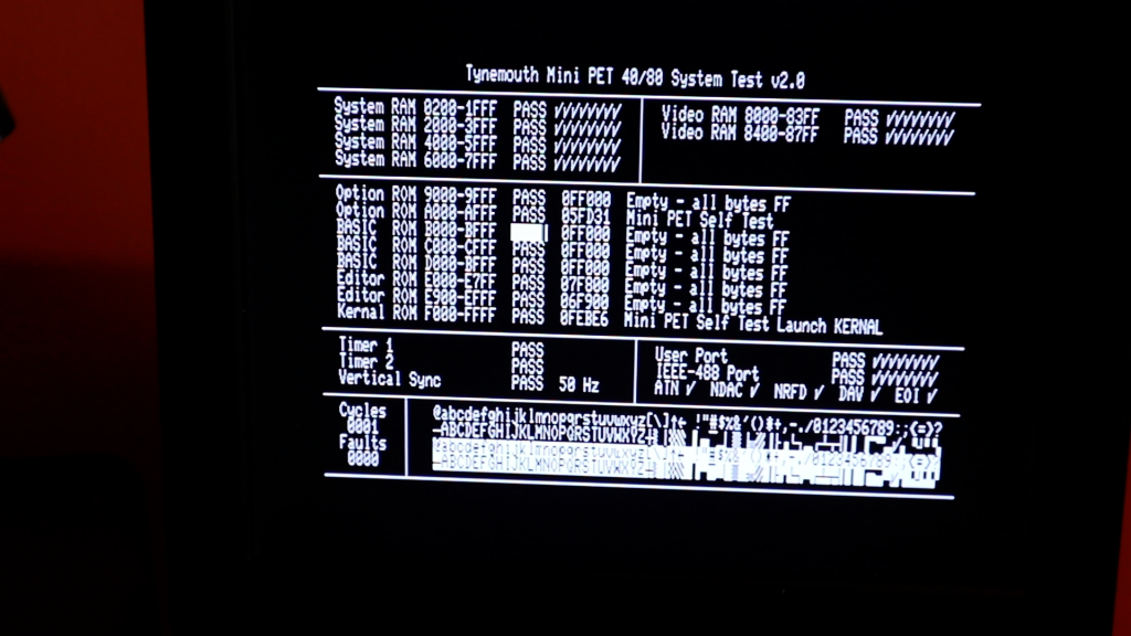
With that done, we can start to use it: run demos, play games, write software….
Oh, and yes I do know the ‘Z’ key is upside down 😉