
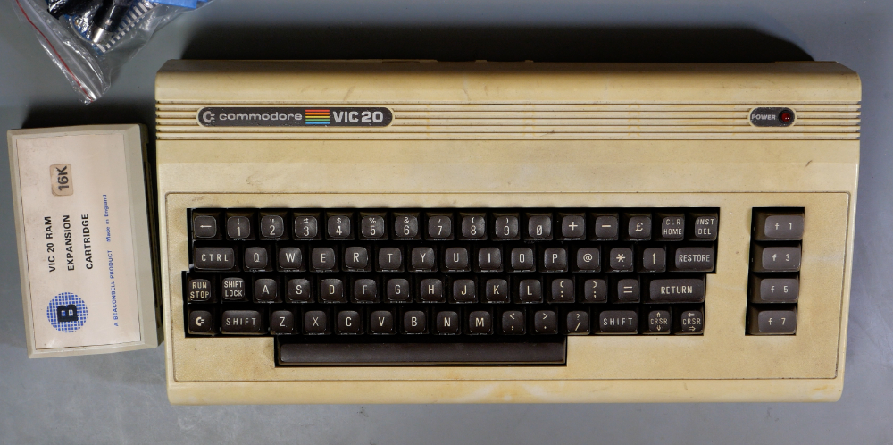
I’m checking out my new (to me) Commodore VIC-20. This computer was sold to me condition unknown, and the case is filthy with some obvious damage to the fastenings. But that’s stuff that can be cleaned, and repaired with a bit of glue and some 3d printing. What I really want to know is: does it work.
Because I have plans for this machine. I want to use it as a test bed for a variety of ICs – 6502, 6522 etc., that can’t easily be tested without something like the Retro Chip Tester Pro (very expensive) or the Backbit Chip Tester Pro (unobtainium). Anyhow, I’m getting ahead of myself.
The Vic didn’t come with any cables, but this model uses the same power supply as a Commodore 64, so that’s no problem. And the same 5 pin DIN video output. So I can plug it in and switch it on. And it works! Or at least it seems to.
In order to be sure, we need to run the diagnostics cartridge. This is similar to the C64 Diagnostics rom. It uses a test harness plugged into all the ports – including the keyboard – to check the signals, and reports anything that’s wrong. From this we can figure out faulty chips etc and replace them. Everything is soldered down on this board, so that will be “fun”. Anyway I run the test.
It fails. “Bad Cassette Motor Signal”.
This is a 9V signal that’s supplied to the cassette pro. The 9V comes straight from the power supply via a fuse, and it’s switched by a signal from one of the 6522 VIAs through a series of transistors. The fuse is obvious: it’s blown. Heck, the fuse holder isn’t even attached properly, so that’ll need to be fixed. With a new fuse, it still fails, so the problem must be somewhere else…
Thanks to www.pcbway.com for sponsoring this video. They produce high quality PCBs, 3D Printing and more starting from just $5. Check them out.